Generating Custom Sine Waves via Headphone Jack Interface
When you are designing electronic circuits, it is often useful to measure the frequency response of its components to the input signal. For example, we might be interested in the attenuation of the 50Hz notch filter. To measure it, we could create a 50Hz signal, feed the filter with it, and compare the spectrums. This information can come in handy when we need to debug the invalid circuit.
Two tools are required to perform such measurements: spectrum analyser and signal generator. These days those devices can be easily purchased in any electronic store. Unfortunately, the price of even entry-level models is somewhat discouraging, especially for people like myself, who are making their first steps in electronics. I have recently emptied my budget on an oscilloscope (Rigol DS1054Z, a popular entry-level model).
Fortunately, unless someone has special needs (such as high-frequency signals above 20kHz), any computer with a sound card and a headphone jack can easily replace both devices. This post describes a simple way to generate a sine wave signal at common frequencies.
What is needed
- a pair of old headphones with a 3.5mm jack,
- a computer (or smartphone), capable of playing youtube videos, with a 3.5mm jack socket,
- [optional] an oscilloscope to measure the signal.
Regarding the oscilloscope, we need it to measure and validate the generated output. You could use your sound card to register the input and use software such as Audacity to process it. I might describe this method in the future.
Connecting the dots
Cut the headphones cable a few centimeters above the plug. Remove the isolation from the tip of the cable, exposing 3 separately isolated wires. Two of those wires are signal channels, and one is a ground. The ground typically has a different color than the rest. Carefully remove one centimeter of isolation from the tips of the ground wire and one of the signaling wires. We are almost ready to generate the signal.
Plug the cable into your device’s headphone jack socket. Connect the scope’s probe to appropriate wires (ground to ground, signal to signal). Open youtube, search for “1kHz sine wave” video, and play it. The complete setup should look something like this:
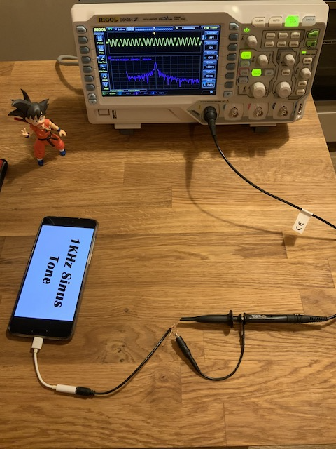
I have already enabled FFT transformation (this varies between scope models, refer to your scope’s manual for information on how to do this). We can see that the amplitude of the signal is around 0.2V, while the most significant frequency component is located around 1kHz. The signal looks nice and sharp, especially considering how little work and money we have put into this.
In the next article, I am planning to describe how to write a custom sine wave generator in python. The custom generator provides more control over the signal than youtube recordings can provide. That’s all for today. I hope someone finds this post useful. This is my very first post, and I’m a rather lousy writer, but I’m planning on getting better, so any feedback is much appreciated. Email is the only way at the moment. I will try to setup some comment system in the nearby future.